Demo Application#
The demo application is a tutor and offers you the possibility to understand in minutes these basic tasks:
Load calibration parameters, that you may have created with the Calibration Tool of the Jumpstart code.
Manage the GPIO for triggering the exposure of the StereoCam Kit Camera Modules.
Grab video using a GStreamer pipeline.
Request the 3D reconstruction to 3D+AI.
Verify the 2D and 3D outputs on your display.
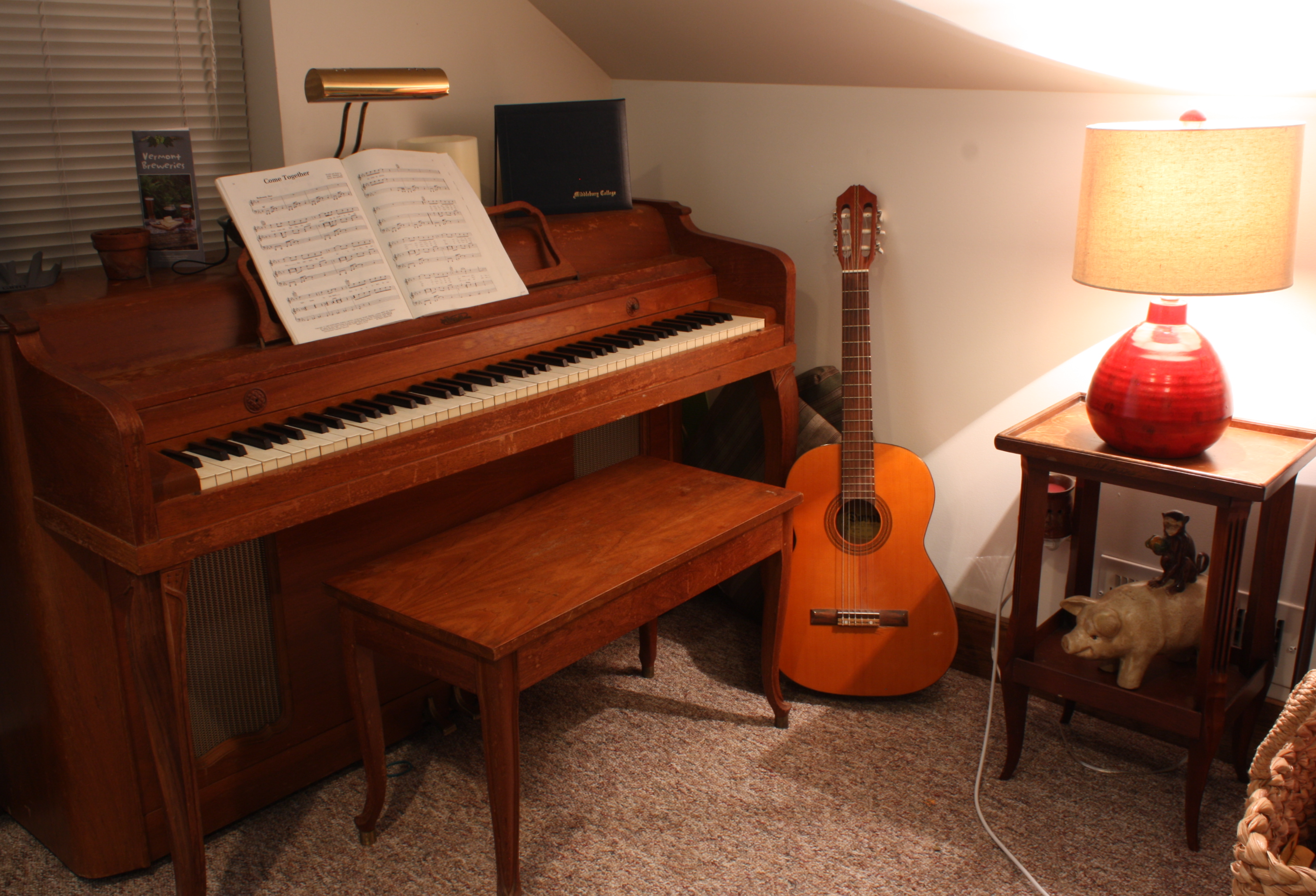
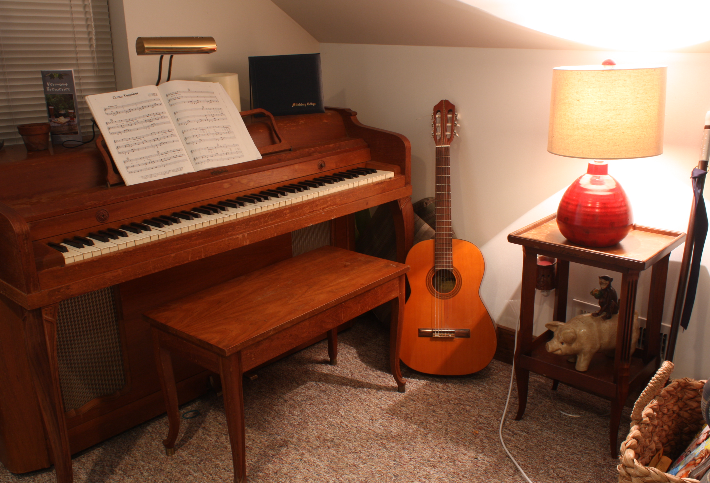
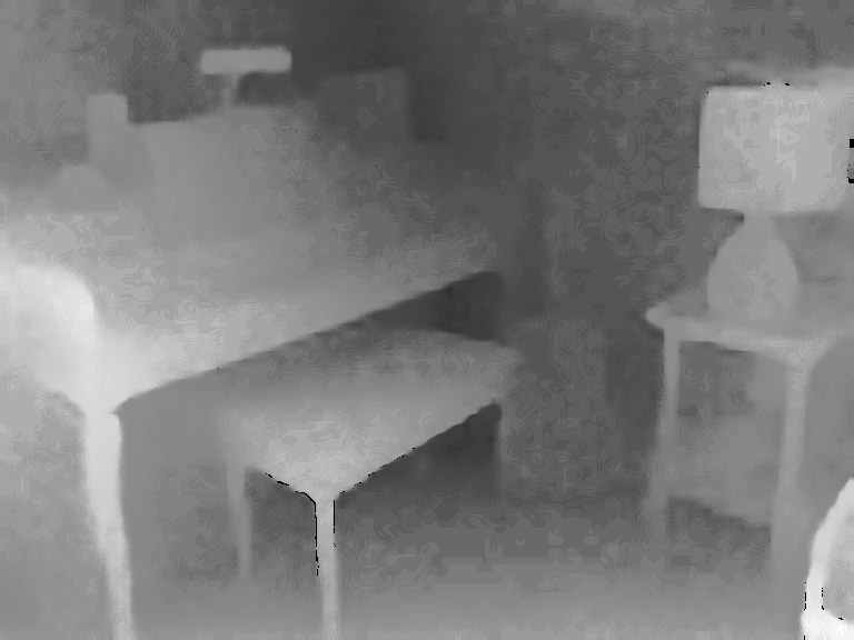
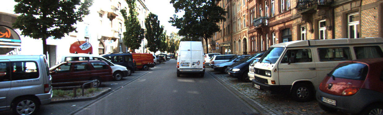
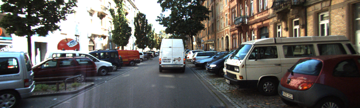
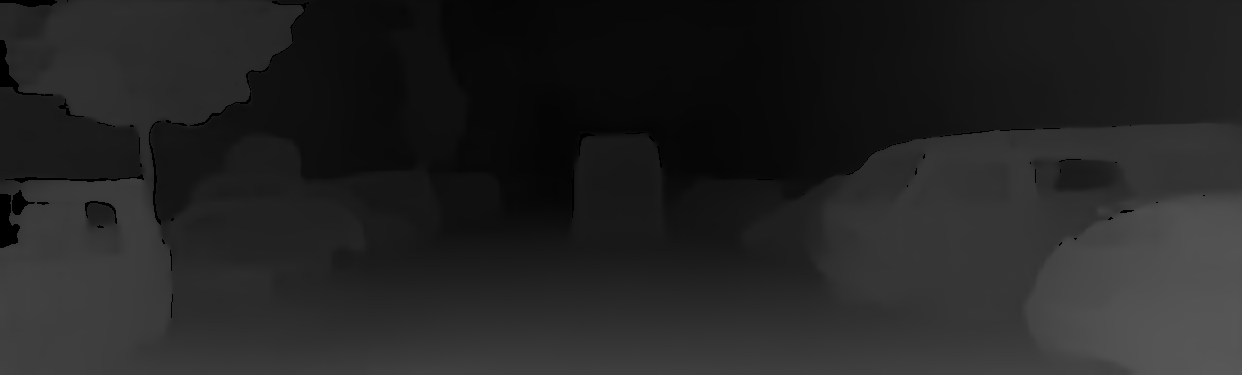
If you properly master the tasks above, you will be able to reproduce metric depth images similar to these:
|
|
Images are taken from Middelbury Stereo Dataset, D. Scharstein, et al. High-resolution stereo datasets with subpixel-accurate ground truth. GCPR 2014 |
|
|
You are strongly suggested to use the demo app to move your first steps, but by no means should it create a limit on 3D+AI and its flexibility of usage.
A few hints and ideas of what you may end up doing through your custom application:
Grab video from network streaming, at no cost of the CPU for video decoding by exploiting the hardware VPU on the i.MX 8M Plus,
Further optimize the processing by porting some of the pre-processing (e.g. video resize) to the 2D hardware accelerator on the i.MX 8M Plus,
Branch the processing, by launching in asynchronous manner on one hand the 3D reconstruction, and on the other an object detection DNN on the RGB rectified video stream from the left camera, at no cost of the CPU by exploiting the NPU AI accelerator on the i.MX 8M Plus;
Raise a digital output of the GPIO to start an alarm depending on some logics based on the metric distance (from 3D) of the detected objects (from object detection on RGB);
Control the whole workflow above, remotely via web services hosted on the local Linux platform, or on local display, through an high-performance GUI that exploits the GPU on the i.MX 8M Plus;
Optimize the Linux image or the usage of the system peripherals by customizing the Yocto recipes;
But let’s put first things first, and start tackling the main points offered by the demo app.
Compile the demo#
As seen in the chapter Getting Started, the demo code is already compiled and you can run it directly from the command line. You can also compile the demo code from scratch.
Note
Here we show how to compile the code directly on the board. The ideal approach would be to create your own cross-compilation toolchain from a custom Yocto compilation. Please refer to deepvision-starterkit-bsp-release.
First you’ll need to clone the demo source code
$ git clone https://github.com/deep-vision-consulting/deepvision-3DAI
To compile the demo you need to use CMake.
Create a build directory inside the deepvision-3DAI folder, and build the demo code by simply running
$ cd deepvision-3DAI
$ mkdir build
$ cd build
$ cmake -DCMAKE_BUILD_TYPE=Release ..
$ make
Now you are able to launch your compiled demo code.
Run the Demo#
With the demo code compiled, you can run it directly with the command
$ ./3dai_demo
To inspect the demo command line arguments add the --help flag.
$ ./3dai_demo --help

Run sample library execution

During execution use keys:
-'q'/'w' to change min depth
-'a'/'s' to change max depth
-'o'/'p' to change sensitivity
- ESC to exit program

Usage: ./3dai_demo [OPTIONS]

Options:
-h,--help                   Print this help message and exit
-c,--calibration-path TEXT REQUIRED
                            Path to stereo calibration (needs to be .json)
-v,--verbose INT:INT in [0 - 4]=3
                            Set log level
-f,--fps INT:INT in [0 - 30]=10
                            Stereo source framerate
--left-image TEXT           Left image filepath
--right-image TEXT          Right image filepath
--use-image Needs: --left-image --right-image
                            Use stereo image source
--stereo-video TEXT         Stereo video filepath
--use-video Needs: --stereo-video
                            Use stereo video source
--left-camera INT           Device index of the left camera (/dev/video<left>)
--right-camera INT          Device index of the right camera (/dev/video<right>)
--use-arducam Needs: --left-camera --right-camera
                            Use stereo camera source
-p,--preset TEXT=res_768_576
                            Preset to be used between ["res_512_384", "res_768_576"]
--no-undistort              Disable input frames undistort
--left-right                Show left/right undistorted frames
--depth                     Show depth colormap
--point-cloud               Show top/side view point cloud
--min-depth FLOAT=250       Set min depth value
--max-depth FLOAT=1700      Set max depth value
--x-range FLOAT=500         Set horizontal point cloud range
--y-range FLOAT=500         Set vertical point cloud range
--sensitivity FLOAT:FLOAT in [0 - 1]=0.45
                            Set result sensitivity
To run the demo on a sample video with the default preset use the following command:
$ ./3dai_demo --use-video --stereo-video /usr/share/3dai/demo_video.mp4 --calibration-path /usr/share/3dai/demo_video_calib.json --left-right --depth --point-cloud
This will run the demo on a sample video, and it will show:
the undistorted left/right input images
the colormap representing the depth
bluefor close pointsyellowfor further away pointblackfor invalid points
the side projection of the point cloud
the top projection of the point cloud
Otherwise if you already have calibrated your cameras (please refer to Calibration) you can use the following command, after substituting with the correct arguments
$ ./3dai_demo --use-arducam --left-camera <left-camera-id> --right-camera <right-camera-id> --calibration-path <path-to-your-calibration> --left-right --depth --point-cloud
To quit the demo press the ESC key on any of the open window.
Note
While closing the demo you may experience some delay, followed by these error codes:
[HailoRT] [error] CHECK_AS_EXPECTED failed - net/resize19 (D2H) failed with status=HAILO_TIMEOUT(4), timeout=10000ms
[HailoRT] [error] CHECK_EXPECTED_AS_STATUS failed with status=HAILO_TIMEOUT(4)
[HailoRT] [error] CHECK_SUCCESS_AS_EXPECTED failed with status=HAILO_TIMEOUT(4) - HwReadElement0_net/resize19 (D2H) failed with status=HAILO_TIMEOUT(4)
[3dai] [error] Internal error: 4011
Don’t worry, the 3D+AI library is working properly. This is a known issue caused by the HailoRT API, and it may be resolved in future releases.
Let’s take a deep dive into each component of the demo.
StereoSrc#
The demo code shows a few example of possible stereo input sources for the 3D+AI library (Image, Video or Arducam cameras). You can test with these sources yourself, or Implement your own stereo source. You can only choose a stereo source at a time, if multiple are chosen an error will be returned.
In the following chapters we refer to left image and right image w.r.t. the camera point of view. Regardless on the kind of stereo source, it should provides a pair of synchronized stereo images to produce a correct 3D reconstruction.
Image#
This is the most simple stereo source example.
The stereo source is created from a pair of stereo images, and each time we ask for a new frame the same images are provided.
Using this stereo source helps to check if the system is working properly.
To run the demo using a pair of stereo image use the --use-image argument,
you also need to specify the absolute paths for the left and right images with --left-image and --right-image arguments.
Video#
This stereo source uses the VPU on the i.MX 8M Plus to decode a MP4 video and provides a frame at a time.
Using the VPU lifts from the CPU the computational cost of decoding the video input, improving performance.
The input video must contain a pair of stereo images, concatenated horizontally with the left image on the left, and the right image on the right.
To decode the input video using the VPU you can use OpenCV with GStreamer backend, in the demo code you can find an example.
std::string gst_pl_tmpl = "filesrc location=\"{}\" ! qtdemux ! vpudec ";
gst_pl_tmpl += " ! imxvideoconvert_g2d ! video/x-raw, width={}, height={}, format=BGRA ";
gst_pl_tmpl += " ! appsink";
// Resize to double the preset width since we have concatenate the left and right images horizontally
const std::string gst_pl = fmt::format(gst_pl_tmpl, stereo_video_filepath, preset_width * 2, preset_height);

auto cap = cv::VideoCapture();
cap.open(gst_pl);
In this example, by using qtdemux followed by vpudec we tell GStreamer to use the VPU to decode the stereo video.
With imxvideoconvert_g2d we use 2D hardware accelerator to resize the images to the preset resolution.
The VPU only supports a limited amount of video decoding, please refer to the official
documentation for more information.
You can use the Jumpstart code example for saving a stereo video, then use it as input for the demo.
Arducam#
This stereo source uses Video for Linux to read from a pair of stereo cameras. In the StereoCam Starter Kit you are provided with two OVM09782 Arducam cameras. To read from one of the cameras you can use OpenCV with GStreamer backend, in the demo code you can find an example.
std::string gst_pl_tmpl = "v4l2src device=/dev/video{} ! image/jpeg, width={}, height={}, framerate=60/1 ! jpegdec ";
gst_pl_tmpl += " ! imxvideoconvert_g2d ! video/x-raw, width={}, height={}, format=BGRA ";
gst_pl_tmpl += " ! appsink";

const std::string gst_pl = fmt::format(gst_pl_tmpl, device_id, camera_width, camera_height, preset_width, preset_height);

auto cap = cv::VideoCapture();
cap.open(gst_pl);
In this example using v4l2src we tell GStreamer to use Video for Linux to read the input camera stream.
You need to specify the device idx to use (i.e. which /dev/video<idx> corresponds to the camera).
You also need to specify the camera width and height compatible with the available camera resolutions.
To check the available camera resolutions you can use the following command:
$ v4l2-ctl -d /dev/video2 --list-formats-ext
We still use imxvideoconvert_g2d to exploit the 2D hardware accelerator to resize the images to the preset resolution.
Implement your own stereo source#
You can implement your own stereo source by extending the demo code.
To do so, follow these steps:
Add a new StereoSrc enum value#
In the stereo_src.h file add the value for your stereo source to the StereoSrc enum
enum StereoSrc
{
    IMAGE,          // Use a pair of stereo image as stereo source
    VIDEO,          // Use pre-recorded stereo video as stereo source
    CAMERA_ARDUCAM, // Use Arducam cameras as stereo source
    YOUR_SOURCE,    // <---- Your stereo source
};
Implement your stereo source class#
Then you need to implement the code for your stereo source.
You need to create a class for you stereo source that publicly inherits from the StereoInput class.
class YourInput : public StereoInput
{
public:
    // ...
    bool get_frame(cv::Mat3b& imgL, cv::Mat3b& imgR) override;

private:
    // ...
};
We suggest you to use the other available stereo sources code as a template, and implement a static create method that returns a unique_ptr to your object.
std::unique_ptr<YourInput> YourInput::create(...)
{
    std::unique_ptr<YourInput> input = std::make_unique<YourInput>();
    // ...
    return std::move(input);
}
Add your stereo input to the demo#
Finally in the demo.cpp file add the required code to parse your stereo source option from command line
First add your stereo source as an argument for CLI11
// ...

bool use_your_stereo_src = false;
app.add_option("--use-your-stereo-source", use_your_stereo_src, "Use your stereo source");
Then add you stereo source to the get_stereo_src function
bool get_stereo_src(bool use_image, bool use_video, bool use_arducam, bool your_stereo_src, StereoSrc& stereo_src)
{
    const bool any_stereo_source = use_image || use_video || use_arducam || your_stereo_src;
    if(!any_stereo_source) {
        // ...
    }

    // ...

    if(use_your_stereo_src) {
        if(made_stereo_choice) {
            spdlog::error("Choose only one stereo option");
            return false;
        }
        stereo_src = StereoSrc::YOUR_SOURCE;
        made_stereo_choice = true;
    }

    // ...

    return true;
}
Finally add your stereo source to the get_stereo_input function
std::unique_ptr<StereoInput> get_stereo_input(const StereoSrc &stereo_src,
                                          const cv::Size &res,
                                          const fs::path &left_image_filepath,
                                          const fs::path &right_image_filepath,
                                          const fs::path &stereo_video_filepath,
                                          int fps,
                                          int left_cam,
                                          int right_cam)

    // ....

    case StereoSrc::YOUR_SOURCE:
    {
        stereo_input = YourInput::create(...);
        break;
    }

    // ...
}
Compile the demo code. Now you should be able to call the demo application using your implemented stereo source.
Calibration#
The --calibration-path argument is used to specify a path to a JSON file containing
the stereo calibration matrices.
To generate this file you can use the Calibration Tool.
If you want to implement your stereo calibration procedure you are free to do so, refer to the Calibration Tool code to see the steps required for implementation.
Below there is a more in-depth explanation on the structure of this file
{
    "K_l": {
        "type_id": "opencv-matrix",
        "rows": 3,
        "cols": 3,
        "dt": "d",
        "data": [...]
    },
    "K_r": {
        "type_id": "opencv-matrix",
        "rows": 3,
        "cols": 3,
        "dt": "d",
        "data": [...]
    },
    "dist_l": {
        "type_id": "opencv-matrix",
        "rows": 1,
        "cols": 5,
        "dt": "d",
        "data": [...]
    },
    "dist_r": {
        "type_id": "opencv-matrix",
        "rows": 1,
        "cols": 5,
        "dt": "d",
        "data": [...]
    },
    "image_size": [ <Width>, <Height> ],
    "R": {
        "type_id": "opencv-matrix",
        "rows": 3,
        "cols": 3,
        "dt": "d",
        "data": [...]
    },
    "T": {
        "type_id": "opencv-matrix",
        "rows": 3,
        "cols": 1,
        "dt": "d",
        "data": [...]
    }
}
If you plan to generate the file yourself, you must provide the nodes described in the snippet above, where:
The node
K_lis the left camera matrix (double 3x3 matrix)The node
K_ris the right camera matrix (double 3x3 matrix)The node
dist_lis the left camera distortion coefficients (double 5x1 matrix)The node
dist_ris the right camera distortion coefficients (double 5x1 matrix)The node
image_sizeis the resolution of the calibration images, which can be different form the library input images (list of 2 integers)The node
Ris the rotation matrix (double 3x3 matrix)The node
Tis the translation vector (double 3x3 matrix)
The library will return CALIBRATION_LOAD_ERROR in case the calibration file does not follow the above scheme.
Otherwise, it can also return INVALID_CALIBRATION if the content of the matrices is invalid.
Verbose#
The --verbose argument specifies the logging level used for printing message to the standard output during library execution.
It accepts an integer value in range [0,4], going from no log information 0 to debug log level 4:
0: Logs are turned off1: Log only error level messages2: Log waning level messages3: Log info level messages4: Log debug level messages
The demo only sets the log level, but the library also allows to save logs to a rotating logging file named log.txt in the current directory.
For a more in-depth explanation please refer to Logging.
Framerate#
You can set the framerate at which stereo images are sent to the library. Depending on the resolution and disparity of the models, or the amount of demo windows displayed, you may want to tune this value. More information on how to monitor the system are in chapter System Status.
Demo Outputs#
The 3D+AI library allows for the user to provide a callback function to process the computed output.
In the demo, we use the VisualizationManager class to show this information on the screen.
The visualization of the library result is influenced by the following arguments:
--min-depth: Minimum depth value. Any depth under this value will be considered invalid.--max-depth: Maximum depth value. Any depth over this value will be considered invalid.--x-range: Maximum distance from the optical center on the x-axis. Used to filter point cloud values.--y-range: Maximum distance from the optical center on the y-axis. Used to filter point cloud values.--sensitivity: 3D reconstruction sensitivity. Determines the amount of confidence required to consider a single disparity value as valid (consequently depth and point cloud).
At runtime you can also press the following keys to update some of these values:
min depth:
q: reduce min depth by
50w: increase min depth by
50
max depth:
a: reduce max depth by
50s: increase max depth by
50
sensitivity:
o: reduce sensitivity by
0.05p: increase sensitivity by
0.05
Here follows a brief explanation on the information displayed.
Rectified images#
By using the --left-right argument, the demo displays two OpenCV windows showing the left and right frames.
These are the resized and, possibly, rectified frames used for the actual 3D reconstruction.
If the --no-undistort argument is provided, the images are assumed to be already rectified and just the resize is performed.
Depth#
By using the --depth argument, the demo displays a colormap of the output depth map.
The color are based on the OpenCV PLASMA colormap: points near to the camera are blue, while points further away are yellow.
Invalid regions are represented in black.
Depth values are normalized between the min and max depth before applying the colormap.
Invalid values are composed of the values discarded by the 3D reconstruction (depending on the set sensitivity), and the depth values that are outside the [min depth, max depth] range.
Point cloud#
By using the --point-cloud argument, the demo displays two projection of the output point cloud.
The first projection is a side view of the point cloud, where the horizontal represents the z coordinate of each point, while the vertical represents the y coordinate.
The second projection is a top view of the point cloud, where the horizontal represents the x coordinate of each point, while the vertical represents the z coordinate.
On the background there is a white grid, with step length defined in the top left corner.
The unit of measurement depends on the size used during the calibration step, for more information please refer to the Calibration Tool documentation.
Points that are are outside the --y-range in the side projection, or outside the --x-range in the top projection will be discarded.
All other points will be represented as white dots.
The left and right border of the side projection correspond to the min and max depth.
The top and bottom border of the top projection correspond to the min and max depth.
Please notice that the dimension of the windows depends on the value difference of the min and max depth.
For this reason decreasing their difference decreases the visualization windows, while increasing their difference increases the visualization window.
Next steps#
In the next chapter you can see how to effectively the 3D+AI library for your custom application.